Showing posts with label Arduino. Show all posts

September 17, 2014

Smartphone Controlled Home

This post describes a low cost open source home automation system that you can build your self. The goal is to use a smartphone as remote controller for your home. The system is based on the openHAB software and MySensors Arduino library.

Home automation enables you to observe and control your home. You can observe temperature, humidity, energy consumption and so on. It will also let you control your lights, media units, window blinds and other objects in your home. You can also create rules based on senors value, time of day or other conditions that will automatically control your home.


Home Automation System Parts
A standard WiFi router is used to connect the smartphone to your local network. The Server (or Controller) is a computer running openHAB runtime core. This is the heart in the system that keeps track of the system. This can be a Window or Linux computer. A Raspberry Pi will do the job. The Gateway (or Access Point) is an Arduino board running the myControler software. The sensor network is a radio network connecting the sensors and the Gateway.

User Interface
Below is a screenshot of the openHAB smart phone user interface. A web browser can also be used.


Security
The openHAB software with enabled encryption and authentication is fairly secure. But the sensor network has very few security features. Since the range of the sensor are limited it should not be a problem unless you live in a densely populated area. I would not connect it to my door lock or something that could cause damage or fire.

References
MySensors - Arduino library for the sensor radio network.
openHAB - Vendor and technology agnostic open source home automation software.

June 13, 2013

Random numbers with Arduino

I was looking for a good random numbers function for Arduino. Here is a summary of what i found so far.

Pseudo-random algorithm

An algorithm that produce a sequence of numbers. It will generate the same sequence every time it is used. The built in Arduino library uses this method.

Sampling an unconnected analog input

The TrueRandom library used this approach. Seems to producing more 0s than 1s.

Independent Counter

The probably_random libray uses two counters with independent sources. Seems promising.

TRNG (True Random Number Generator) module

The Atmel SAM3X8E on Arduino DUE has a dedicated block for random numbers. There is a library available for this: advancedFunctions.

April 26, 2013

Stop motion with Pentax K5 and Arduino


Sebastian Setz has created an Arduino library that can emulate an IR remote for a system camera. It supports all major brands. I created a sketch that takes a picture when i push a button. I used it to create a stop motion movie where it is important not to move the camera between shots. This library could also be used to make time laps shots where the camera takes pictures at a defined interval.

Below you can see my set up for the stop motion. To make a video of the jpg images i used MakeAVI.


Here is the video.
 

April 16, 2013

Develop for Arduino on Android - ArduinoDroid

ArduinoDroid is an Arduino development environment (IDE) for Android providing (almost) the same functionality as the computer version. Almost since not all boards and functions are supported yet. An OTG cable and Android device capable of OTG are needed to upload code to the board.

I loaded the app on my Sony Xperia V and compiled the blinker example.Then I connected the Arduino UNO and upload it without problems! A great job done by Anton Smirnov that develops this.

My set up.
 

Screenshot

April 9, 2013

Arduino Pro Mini low power modification


In this post I use an Arduino Pro Mini 5V 16 MHz MEGA328 powered by an external 5 V source. My application will run on a small battery so I need to minimize the power consumption. I measured the board to consume about 16 mA in normal operation.

My application can be in sleep mode until an event occurs. This is how to enter sleep mode:
set_sleep_mode(SLEEP_MODE_PWR_DOWN);
sleep_enable();
sleep_mode();


Make sure to used this include:
#include <avr/sleep.h>

Wake-up from sleep mode is done with an interrupt. That part is not covered in this post. In sleep mode I measured the current consumption to be 476 uA (microampere). To improve this is I did the following:
  1. Disabled the power on LED by removing the current limiting resistor. It got down to 152 uA.
  2. Removed the unused on board 5 Volt regulator to avoid leakage. This resulted in 136 uA.
The picture below shows the positions of the components that I have removed.

The battery that I will use is a 3.7 V 230 mAh Li-Po regulated by a TI TPS61200 Boost Converter. With an assumed efficiency of 90% I get 230 * (3.7 / 5) * 0.9 = 153 mAh. This gives the theoretical time of operation:

Sleep mode before: 476 uA => 321 h (~13days)
Sleep mode after: 136 uA => 1125 h (~46 days)
Normal operation  mode: 16 mA =>9.5 h

Conclusion: The improvement of the modification is about 3.5 times longer standby time in sleep mode. I was hoping for a month of standby time so with the improvements it should be enough for my design.

April 4, 2013

Monochrome 128x32 OLED Display

I purchased a tiny OLED display from the eBay seller wide.hk that also have a webpage. The dimensions for the module is about 13x34 mm and the interface is I2C.


Here is how to get the display running with Arduino. Download and install both these adafruit libraries:
https://github.com/adafruit/Adafruit_SSD1306
and:
https://github.com/adafruit/Adafruit-GFX-Library 

Hint: use the ZIP button on the github page to get all the files.

For installation instructions see my previous post.

Open the example ssd1306_128x32_i2c in the Arduino software. When compiling you will probably get this error mesage "ssd1306_128x32_i2c.ino:53:2: error: #error ("Height incorrect, please fix Adafruit_SSD1306.h!");"

To fix this open the newly installed library file: Adafruit_SSD1306.h
Find these lines in the file:
   #define SSD1306_128_64
//   #define SSD1306_128_32

change them to:
//   #define SSD1306_128_64
   #define SSD1306_128_32

Save the file and compile again. This time it should complete without errors.
Hint: Use CTRL+R to compile.

Connect your display to the Arduino UNO as follows:
  • ⏚ to GND
  • + to 5V
  • SDA to A4
  • SCL to A5
The library is also using pin 4 as reset. This display does not have a reset terminal so just leave it unconnected.

Upload the code to the Arduino and your display should wake up!
Hint: Use CTRL+U to Upload.

March 13, 2013

Energia a port of Arduino IDE for TI MSP430

Energia is a port of the Android software for the TI MSP430 LaunchPad. My LaunchPad with a MSP430G2231 has mostly been collecting dust lately so i decided to give it a try. My first test was the provided blink a LED and serial communication examples and as expected they worked fine. So I decide to try something a little more challenging.

I installed my library from the previous post and hit compile. There was no errors but the pin assignment needed to be updated for the MSP430. I did the changes below and downloaded it to the LaunchPad.
const int loadPin  = P1_4;
const int sdataPin = P1_5;
const int sdclkPin = P1_7;

As you can see in the picture below it worked. Energia is a promising software. The latest version on the web page is a bit old but the git repository seems to be updated lately and the forum is quite active so hopefully the work will continue.

March 6, 2013

Arduino library for Osram SCDQ554xx Displays

This is a description of my Arduino library for Osram SCDQ554xx Displays. The library is available for
download here. For installation instructions see my older post Installing newping library.

The device that I have used is the SCDQ5542Q. But the following devices should also be supported:
  • SCDQ5541X (Yellow)
  • SCDQ5542X (Super-red)
  • SCDQ5543X (Green)
  • SCDQ5544X (High Efficiency Green)
The display is a tiny LED display with 4 characters with a 5x5 Dot Matrix. The device has no built-in character definition instead each dot is individually programmed to be on or off.


My libray has an example with the numbers 0-9 and decimal point defined. Other symbols can easily be added. For character sets and other details see the Data sheet. 

March 3, 2013

Review of Arduino Ethernet Shield W5100

You have probably seen the non official low cost Arduino Ethernet Shield from China or Hong Kong with the WIZnet W5100 chip that you can get for about $10. So are they any good? I ordered one to see. It arrived intact after a month packed in a solid cardboard box but without any ESD protection.The build quality seems to be good.

I loaded the WebServer example and hooked it up to my network and it worked immediately without any problems.


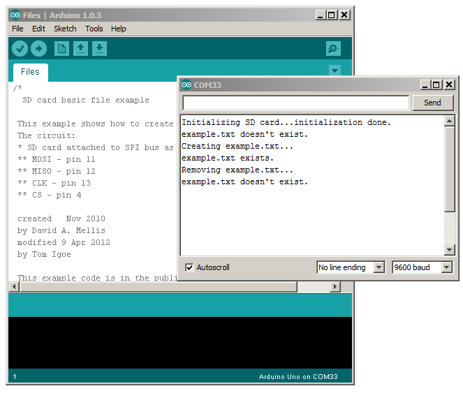
I also tested the SD card interface with two of the examples provided by the Arduino software. The first test was with the SD card basic file example (files).
The second test was SD listfiles example. Note that you need to edit this example to run it with the Ethernet shield since it is written for usage of pin 10 instead of pin 4. Simply search for "SD.begin(10)" and replace it with  "SD.begin(4)". Below is the result with a card from an old Android phone.
When buying the Shield it is advertised to have the MAC address: 0xDE, 0xAD, 0xBE, 0xEF, 0xFE, 0xED (Note the hacker humor "dead beef feed") but this is not true since it set by your Arduino code. Sure this is the default value for MAC address in the examples but you can set it to whatever you like. If you have multiple devices on the same network it is probably a good idea to set it unique for each devices since the router might be confused otherwise.


Pros:
+ Low cost.
+ Works with the SD and Ethernet examples in the Arduino software (Tested with 1.0.3).

Cons:
- You are not supporting the creators of Arduino but the design is open source so anyone can build and sell them legally.

February 26, 2013

Arduino IR remote library

If you have an Arduino project where you need to handle remote control infrared signals you should have a look at IRremote library by Ken Shirriff. It recognizes many commonly used protocols and can also capture and send raw data for unknown protocols. Download it from his github page:
https://github.com/shirriff/Arduino-IRremote

I used the provided example named IRrecord to receiving and transmitting codes with my Panasonic TV remote. It was recognized as raw and it worked well to learn codes and send it to control my TV. A clever trick to see if you transmitter is working is to use your smart phone camera. Looking at the IR led in the camera viewer enables you to see the IR light.
Here is how to wire the sensor and the IR led, the button is is used to send the last captured code.


By opening the serial terminal the captured code can be viewed. It shows the length of the mark and space in the code.

February 20, 2013

Connecting Arduino to MK802 running Lubuntu


I had an idea of combining a MK802 running Linux with an Arduino UNO to get some I/O pins controllable from the MK802. This post describes how to do serial communication over the USB cable with a terminal application and with Python.

Boot Lubuntu and login then connect the USB cable from the Arduino to the MK802 and open a LXTerminal and type:

dmesg

It will print of lot of information but look at the end for lines similar to these:

[  217.500000] cdc_acm 3-1:1.0: ttyACM0: USB ACM device
[  217.510000] usbcore: registered new interface driver cdc_acm
[  217.510000] cdc_acm: USB Abstract Control Model driver for USB modems and ISDN adapters

This means that you Arduino is mapped on the device name ttyACM0. To open a serial terminal to this device type:

screen /dev/ttyACM0

If screen is missing install it by typing:
sudo apt-get install screen

Below I have run screen with the example "Communication -> ASCII table" from the Arduino Software. I prepared the Arduino UNO with the code on a Windows computer before  I connected it to the MK802.


The serial communication can also be done with a Python script. Create a file named Arduino.py with the lines below it an run it with:
python Arduino.py

import serial
ser = serial.Serial('/dev/ttyACM0')
while 1:
  while ser.inWaiting() > 0:
    print ser.readline()
 
It should result in a something similar to the picture below.

February 15, 2013

Installing NewPing library for Arduino

Just for fun I decided to play with an ultrasonic sensor for distance measurement and an Arduino. The sensor that i used is the HY-SRF05. The included example for Arduino is written for the Parallax PING sensor. The HY-SRF05 is a bit different from the PING in the sense that it uses two pins for communication instead of one. This is not supported by the default example. But luckily there is a good alternative. The NewPing library has many features and support the HY-SRF05. It is available for download from here: http://code.google.com/p/arduino-new-ping/

The installation of an Arduino library is easy. Just unzip the library files in your Windows Documents folder in the folder Arduino\libraries\<LibName> as illustrated below.


The library integrates well in the Arduino Software and comes complete with examples.

The HY-SRF05 runs from 5 Volts so it is easy to use with the Arduino. The trigger pin is connected to pin 12 and echo pin to pin 11 on the Arduino. This is how it looks when it is running.
The accuracy of the sensor seems to be fairly good but I did not evaluated that throughly.

January 30, 2013

Fritzing - Veroboard and Breadboard design software


If you are looking for a free tool to create schematics and documentation for your prototypes, Fritzing may be right for you. It can also be used to created and manufacture PCBs from your design. Frtizing has three views that share and automatically update a netlist so that if a component or connection is made in one of the views it is also added in the other two. The views are called Breadboard, Schematic and PCB.


In the Breadboard view your design look and feel like physical objects. It has regular components like resistors, capacitors, inductors and ICs. It also has cables, Veroboard, Breadboard and blocks like an Arduino, sensors, servos, motors and many more.

The Schematic view is a traditional electronics schematics editor. As mentioned Fritzing has the most commonly used components and modules in the built in library but if your favorite part is missing it can easily be added. I added the JY-MCU Bluetooth module from my previous post by modifying an existing component within minutes.Download it here.

I felt that Fritzing is easy to use and learn. But it was not obvious to me how to cut the lines on a strip board. It turned out that it is quite simple, right click betweens the holes as illustrated with the arrow in the figure below.
I did not try the PCB design part at this time. Fritzing installer package are available for download from: http://fritzing.org

January 25, 2013

Bluetooth with Arduino

I recently purchased a low cost Bluetooth module with serial interface. I decided to hook it up to my Arduino.

Arduino UNO does only have one UART that is used for the USB serial terminal so it can't be used but there is a Software UART available that uses regular I/O-pins. For details see:
http://arduino.cc/en/Reference/SoftwareSerial

It works well at 9600 baud but when i tried 115200 the reception failed and received characters was corrupted. This worked in my previous test both with an FTDI cable and a Bus Priate.

The baud rate of the module can be changed by sending a AT command before connecting to the module to a Bluetooth device. The command is:

AT+BAUD<index>

Where <index> is an hexadecimal number from 1 to C. The rates are: 1:1200, 2:2400, 3:4800, 4:9600, 5:19200, 6:38400, 7:57600, 8:115200, 9:230400, A:460800, B:921600, C:138240

WARNING: Do NOT set it higher than your device is capable of since you will need to communicate at the new rate after sending this command. I used an FTDI cable for changing back the configuration. 

The board is marked "JY-MCU BT_BOARD v1.03". The supply voltage is stated to 3.6 - 6 V on the board. But the RX and TX terminals are 3.3 Volt logic. Therefore a voltage divider as shown in the figure below is need for the TX output on the Arduino when connecting it to RX on the module. The TX on the module can be connected directly to the RX on the Arduino. I have put the two resistors on a veroboard.The values are R1=10k and R2=20k.

Below is the Arduino code I used for the tests. It transmits received Bluetooth data to the USB terminal and vice versa.


#include <SoftwareSerial.h>
const int RxPin = 10;
const int TxPin = 11;

SoftwareSerial Bluetooth(RxPin, TxPin); // RX, TX

void setup()
{
  // Open serial communications and wait for port to open:
  Serial.begin(9600);
  while (!Serial) {
    ; // wait for serial port to connect.
  }
  Serial.println("Init done!");
  // set the data rate for the SoftwareSerial port
  Bluetooth.begin(9600);
}

void loop() // run over and over
{
  int data;

  if ((data = Bluetooth.read()) != -1)
   Serial.write(data);


  if ((data = Serial.read()) != -1)
   Bluetooth.write(data);
}